Exploring a cross-polarised photogrammetry workflow in a heritage context
Adam Frost, Clara Molina Sanchez, David Vacas-Madrid, Elina Rodriguez Millan, Sophia Mirashrafi
It is a universally acknowledged truth in the field of 3D data capture that documenting shiny items is a challenge, to say the least. Glossy finishes that return specular (or mirror-like) reflections complicate capture techniques that rely on light, from laser scanning to photogrammetry.
At Historic Environment Scotland (HES), as part of the Rae Project, we are committed to digitally documenting our 336 Properties in Care and the 40,000+ collections objects they house—many of which have ceramic glazes, polished metal varnishes, and other inconveniently reflective or glossy surfaces.
The character of the reflection is important, possibly indicating condition or telling us more about the object’s material properties. So ideally, the 3D model should reflect the actual artefact as closely as possible, which includes capturing them in their full shiny glory.
Working with the team at Spectrum Heritage, we explored a workflow that would allow us to do just that: cross-polarised photogrammetry.
What is cross-polarised photography?
‘Cross-polarised’ photography is essentially a workflow used to achieve reflectionless photography using ‘polarised’ light. Some light, such as natural sky light, is already strongly polarised through the effect of the sun’s light scattering in the sky. Photographers can use filters in front of the camera to strip out this polarised light, removing strong sky reflections from surfaces like glass and water.
When polarised light hits a rough surface that diffusely reflects light, most (if not all) of that light will become unpolarised. However, smooth microstructure surfaces, such as glass, glazed ceramics, and many plastics, can reflect light (often referred to as ‘specular’ reflections) in a way that maintains the light’s polarisation.
Cross-polarised photography has in recent years emerged within the wider 3D capture community as a recognised way of removing ‘specular’ reflections from surfaces of photographed objects. In principle, this takes care of the negative impact that reflective surfaces have on data processing by removing any shine. But what if we want to keep the specular information, a valuable asset enriching our record of the item?
To address this, we developed a modified cross-polarised photogrammetry workflow that, instead of just removing the ‘specular’ reflective component, would isolate and develop it into a reflection map, all while stripping the glare of the lighting from the diffuse map.
We wanted to explore whether this would be compatible with our current photogrammetric workflow and identify the benefits to conservation and visualisation. A range of objects were chosen for their varied material properties (including wood, ceramic and metal) to explore the performance of the cross-polarised technique on materials that may not have an obvious application. It’s worth noting that polarised light, and cross-polarised inspection methodologies, already see use in the field of conservation from thin section microscopy, to assisting with the identification of colour pigments in paint.
The key aspects of our workflow comes to you in two parts: the capture and the post-processing.
The Capture
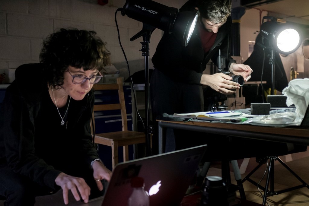
The setup was similar to a typical photogrammetric approach for digitally documenting collections items. Above, Clara Molina Sanchez and David Vacas Madrid are in the midst of the capture of a collections item in HES storage.
In terms of hardware, we used a remotely triggered DSLR controlled by a laptop, a turntable, and relatively diffused two-point lighting. Colour calibration charts were used alongside metric distance scales to ensure colour-accurate textures and measurable, correctly scaled geometry.
To enable the cross-polarised workflow, we used 3D printing to create bespoke filters to hold linearly polarised film, which could be rotated to dial in the angle of the incident light. Two LED flash lights were used, with linear polariser film placed over the flashes, and a polariser filter likewise placed on the camera lens. The polariser filter was then rotated until perpendicular to the polariser film, thereby achieving a “cross-polarisation”.
To calibrate the polarity of the incident light, a glossy black ball was placed within the frame initially to enable us to align the two light sources relative to the lens filter.
It’s important to note here that this was a time intensive process, each object taking a day to capture properly. Each photograph had to be taken twice: one photograph with the full specular reflections, and its twin with reflections removed by rotating the filter 90 degrees (non-polarised and polarised respectively).
The Post-Processing
RealityCapture
Back in the office, the photographs were processed into 3D models using Reality Capture. To do that, both the polarised and non-polarised images were imported and aligned as part of the same project, only using the polarised images to create the mesh to avoid those troublesome reflections.
To texture the mesh, the non-polarised images were used initially, before repeating the texture process with the polarised images. This produced two diffuse texture maps with identical alignment. For the final diffuse texture, we used the albedo map without reflections. To calculate the ‘reflection’ map, the resulting two textures could then be overlaid and subtracted as described in the next section.
Texture map creation
The different maps applied to the models is what really does the hard work in making the 3D representation as close to reality as possible. Physically based rendering (PBR) refers to the concept of using realistic shading and lighting models along with measured surface values to accurately represent real-world materials. This is a rendering method currently used by most 3D software and web viewers, like here on Sketchfab.
We made the specular map from the polarised and cross-polarised diffuse maps by calculating the difference between the two. Any raster image editor could produce these maps, but for this project we used Substance Designer and Adobe Photoshop.
As material shaders on various platforms handle input values in their own way, the difference maps often needed further processing and tweaking in the image editor so we could tailor them to the final output.
The workflow below illustrates these stages.
Specular
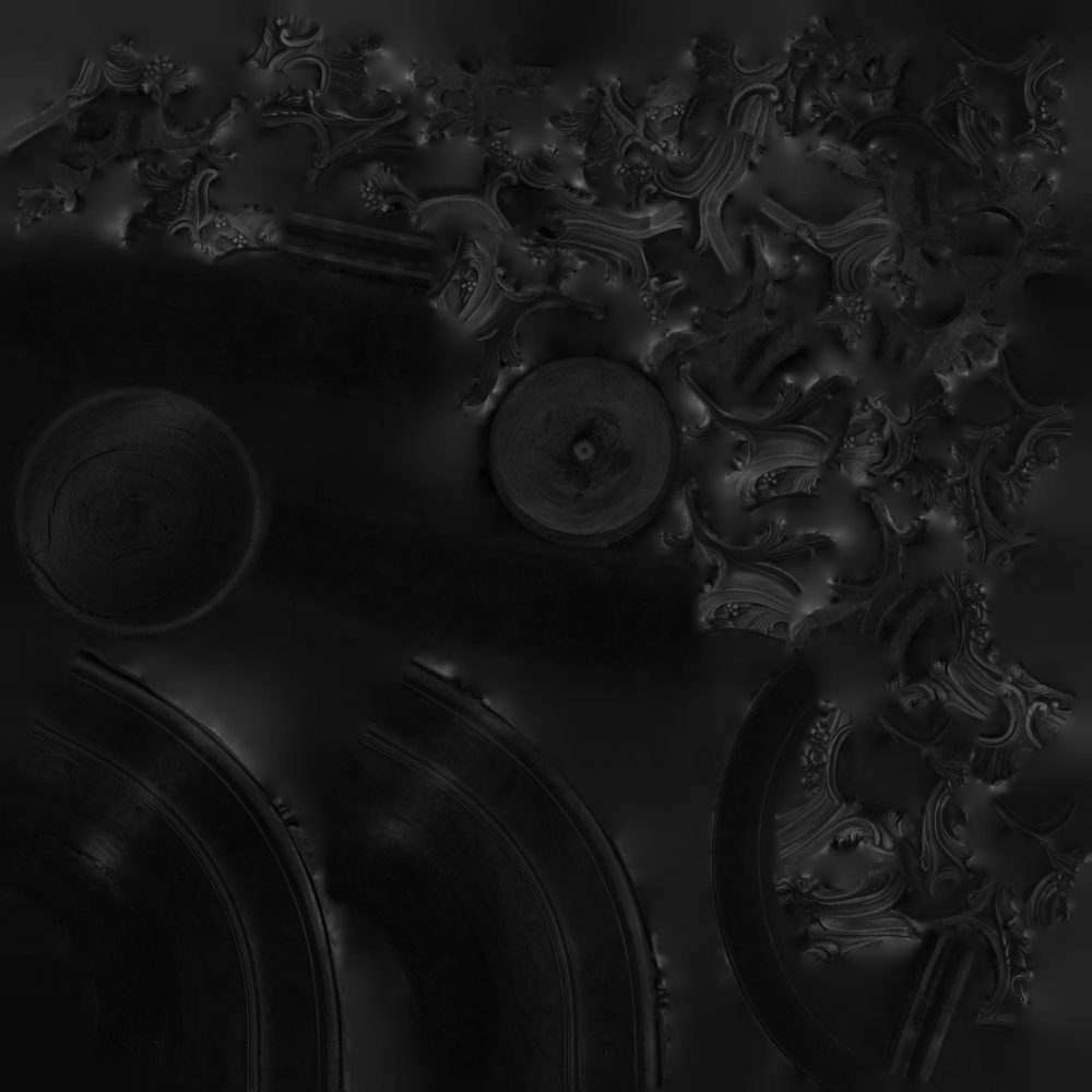
This map contains the reflectance information from dielectric (or non-metal) surfaces. Areas that are black are shown as completely matte, while white areas are completely reflective, letting the software know where the reflections should and should not appear.
To achieve this, we overlaid the two diffuse textures derived from both the polarised and non-polarised images, calculated the difference and converted that difference to greyscale in Substance Designer. The greyscale map produced through this image-difference process should represent the intensity of specular reflections captured on the object’s surface.
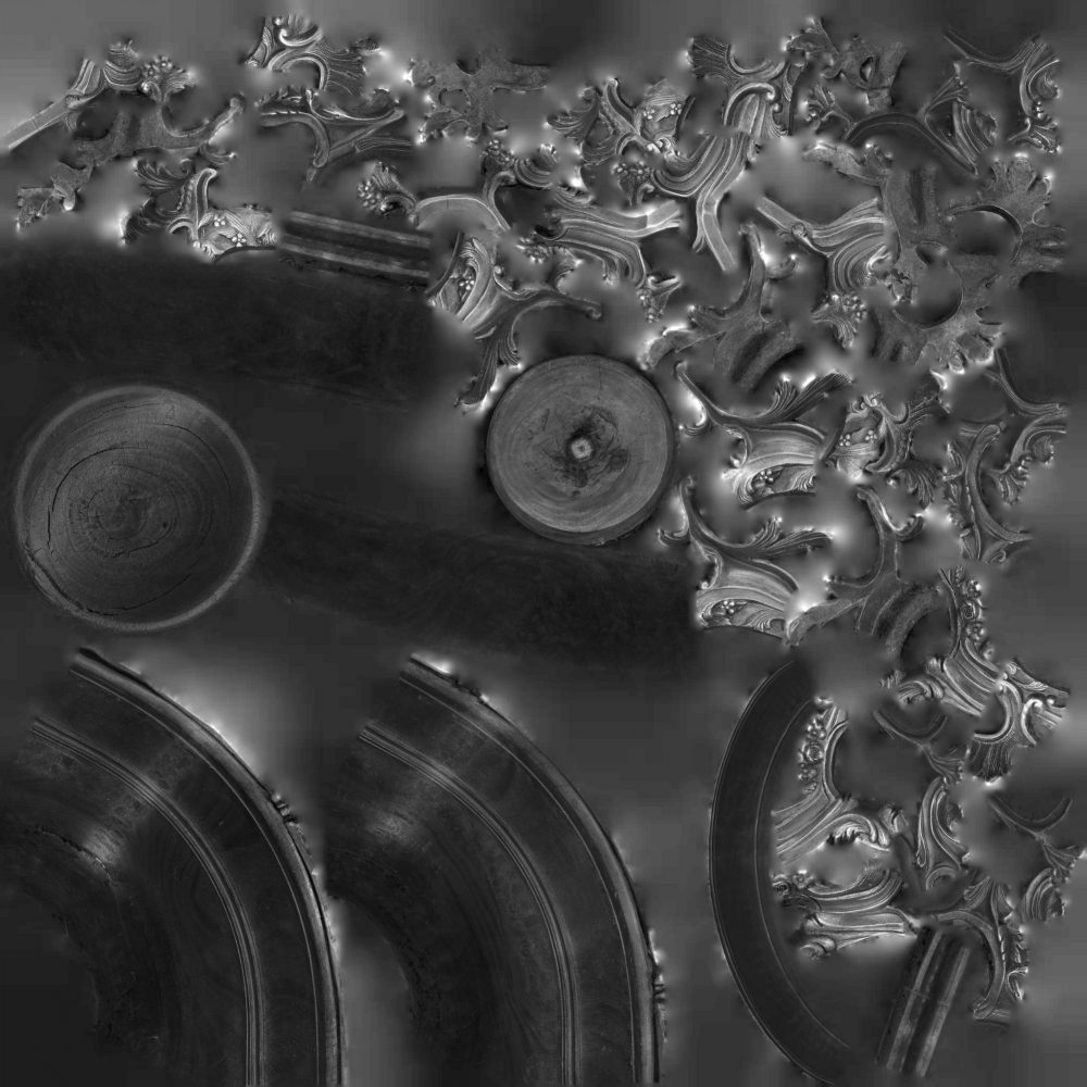
This raw ‘reflection’ map will need further image processing to ensure that the reflection output will be interpreted and rendered correctly when it is used within the material shader. The extent of this image processing will vary depending on a range of factors, including the initial capture conditions, the material shader, and the final output platform.
Roughness/Glossiness
These maps describe the microsurface of the object and control the ‘sharpness’ of the reflections. White areas represent roughness, while black areas indicate smoothness. Because the specular map contains blacks levels that are too high for differentiation by Sketchfab, the histogram was tweaked slightly, moving the levels to the area with the most information. This obtains a greater contrast, helping Sketchfab recognise the roughness of the surface more effectively.
Metallic
This map tells the shader if something is metal or not, with metal represented in white and non-metal in black. There can be transitional grey values that indicate something covering the raw metal, such as dirt. This map is generated when there are metallic areas on the object. As with the roughness/glossiness map, the levels are tweaked to enhance the appearance in the Sketchfab material shader.
Last Touches
Whatever the workflow, normal and ambient occlusion (AO) maps are integral to completing the models. The normal baked in gives the optimised model all those sweet micro-details found in the surface and the AO map makes it possible to simulate the soft shadows that occur in the cracks and crevices of an object, giving more depth to the retopologized mesh.
Final thoughts
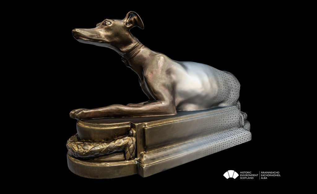
Overall, while the workflow proposed is not unlike our standard photogrammetry workflow, this method of capture provides information that our usual techniques would miss. In some cases, the imperfections on the surface that are only revealed with these reflections can completely change the appearance of the object.
For instance, explore the scratches visible in this tile’s reflection because of the reflection map generated in the PBR shader.
In addition to improving the visualisation of the items through richer material shaders, some potential conservation applications could include:
- Documenting the condition of reflective surface finishes such as varnishes and glazes, for example, where crazing is visible.
- Recording and visualising reflective metallic surfaces and distinguishing them from oxidised or patinated areas for condition assessment.
- Capturing ‘micro-structure’ surface scratches, which may otherwise not appear in standard capture.
- And finally, the documentation of reflective (e.g. glossy varnish, polished metallic) collections items where specular reflections negatively influence the reconstruction of accurate 3D surface geometry.
These results are promising, and open exciting possibilities for documenting objects that could not be accurately digitized using standard photogrammetry. This workflow can be tricky, and we have only “scratched the surface” here. The maps produced with our workflow have been used to improve the visualisation of these objects and should not be considered absolute values, each varying according to the processing workflow and capture setup. There are many aspects that require further research to create a standardised workflow, and we look forward to exploring it further in future.
Check out the whole collection here on Sketchfab!
Cross Polarised Collection by Historic Environment Scotland on Sketchfab

