3D Artists Kathrin Lipski and Christian Lipski stop by to share some hot tips on how to streamline your photogrammetry workflow. This article was originally published on Christian’s website.
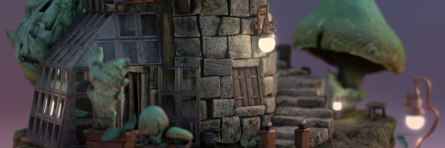
For our latest personal project, we experimented with combining traditional scale modeling and digital tools. We wanted to create a lighthouse on a floating island. We have been playing with this concept for quite a while and decided to go for a look that is reminiscent of scale modeling and miniature dioramas. The first idea was to build a scale model and add a few hand-modeled 3D objects. After some failed attempts at putting real-world bricks together, we decided to scan the individual building blocks and put them together digitally. We build some cube-shaped bricks from salt dough and painted them with some long-forgotten techniques of ink washing and dry brushing we know from miniature painting. For the plants on the island, we strove for a look that is somewhere between realistic and fantastic. We scanned mushrooms, ginger, an artichoke, and a leaf and used some 2D image manipulation to give them a greenish bioluminescent look.
We used photogrammetry to digitize the real-world objects and were faced with the daunting task to scan 30 individual objects for the virtual diorama. Having never scanned so many objects for a single project, we decided to revisit some steps of our photogrammetry workflow and share the results with you. All 3D scans were performed on a simple turntable stage, so these tips are all geared towards a studio setup where you can control the position of the object, the lighting, and the background (and by “studio”, I mean occupying our kitchen table for several days). You’ll find both the individual PBR (physics-based rendering) assets and the final result of this project on Sketchfab, We release them under the very permissive CC-BY license and would be thrilled if they help you realize your own ambitious project.
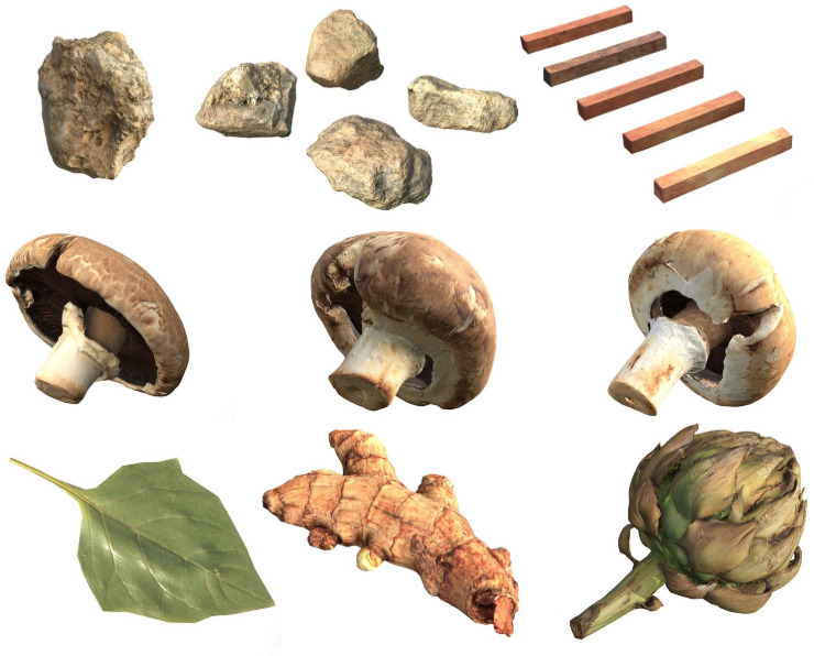 All 30 assets scanned for this project: 16 bricks, 5 rocks, 5 sticks, 3 mushrooms, a leaf, ginger and an artichoke. Scroll down to the bottom for the complete collection on Sketchfab.
We used both RealityCapture and MetaShape for the scans. While a few tricks are specific to these individual software tools, all results should be easy to reproduce with other photogrammetry software packages like Zephyr or Meshroom. We assume some basic familiarity with your tool of choice and won’t explain the basic operation of your tool. If you are a photogrammetry rookie (and are still reading this article) we applaud your determination but would like to encourage you to also have a look at some more basic tutorials to close any knowledge gaps.
1. Foreground Separation
We think that having decent lighting, an appropriate background, and a turntable (even if it’s not motorized) is just as important as having a good camera and lens equipment. Since some light bulbs and white copy paper cost much less than a fancy DSLR, you should definitely invest in this area before getting a camera upgrade. First of all you should get some decent lights that do not cast strong shadows, we suggest getting two softboxes that illuminate the objects from all sides. We highly recommend using a turntable for your scans, a manual one (i.e. one that isn’t motorized) will do just fine. Put marks in regular intervals on the turntable. We marked 80 possible positions ours so we can easily capture 80, 40, or 20 photos during a full 360 revolution. For ‘easy’ objects we tend to capture fewer photos. For more challenging ones we use all 80 available positions. We use a tripod for all studio shoots.
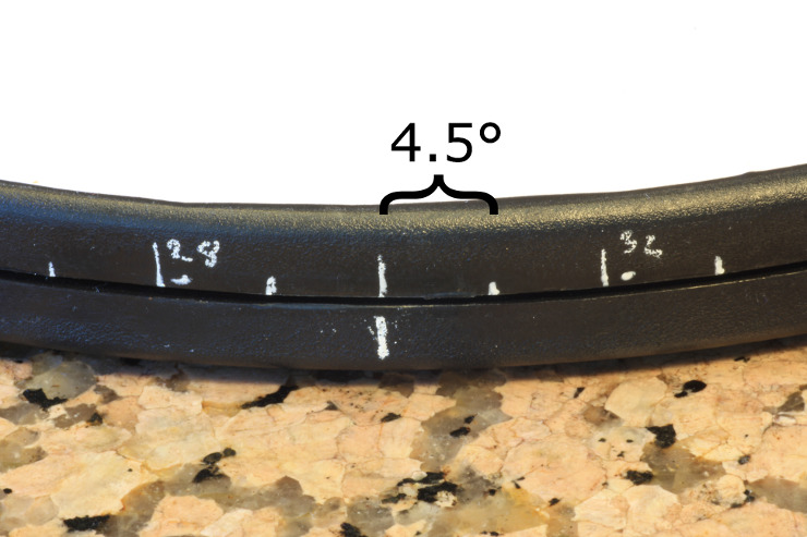 The turntable is covered with plain white copy paper. We put white marks at regular intervals, so we can easily make sure to do 20, 40 or 80 photos per full rotation.
For the background, pick anything that does not have a strong texture and is, either way, brighter or darker than your scanned object (avoid green screens, they introduce color spill that you won’t enjoy having on your object). If foreground and background are distinguishable by brightness values, it will be much easier to process the scan (see the texture swapping section). We always recommend going for a white background if possible: A white background will allow for more light to be bounced back to your object and produce cleaner scenes.
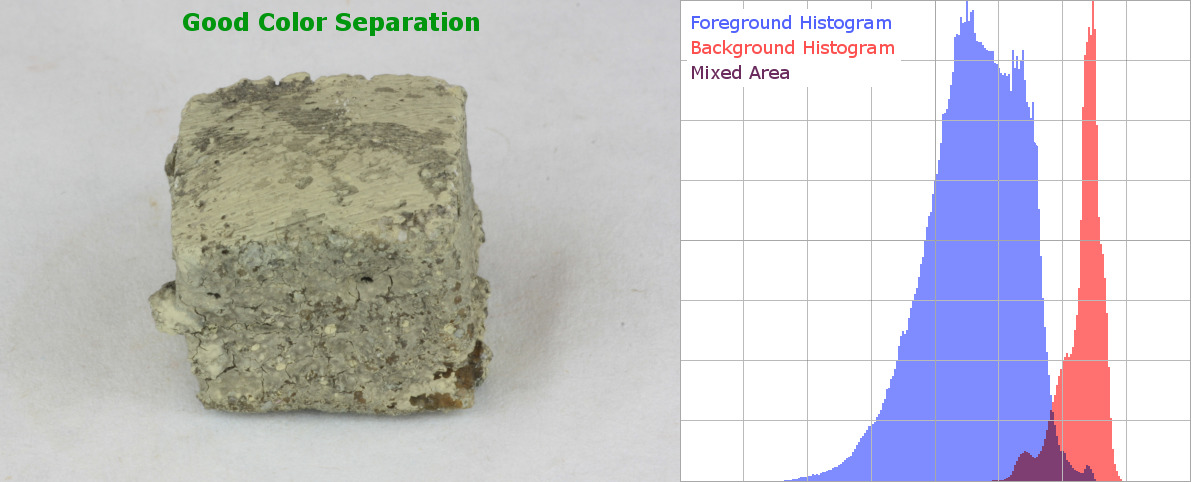
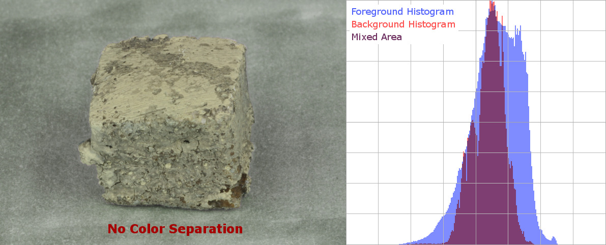 “No Color Separation” shows that a gray object on a gray background is not ideal. While most photogrammetry software will produce decent results with this kind of material, we recommend using a background that is easy to distinguish by brightness value (“Good Color Separation”). This will make it way easier to manually (magic wand tool) or automatically (threshold – brightness/contrast modification) exclude background information from further processing.
 When using copy paper as your background, you can even boost its brightness by using additional UV bulbs (should be around $10) for your lighting. Copy paper is fluorescent, so any UV light shining onto it will be turned into visible blue light. When you have very bright objects to capture, black backgrounds might work just as well. Be aware that underexposed regions will rarely have a brightness of 0 but will typically show a very noisy pattern that might confuse the photogrammetry software. Also, you might have to illuminate the scene a bit more.
2. Maximum Overlap
In order to get the best results, make sure that every photo has sufficient ‘overlap’ with the rest of the data. By that, we mean that there should be multiple other photos that see the same part of the object from roughly the same distance and angle.
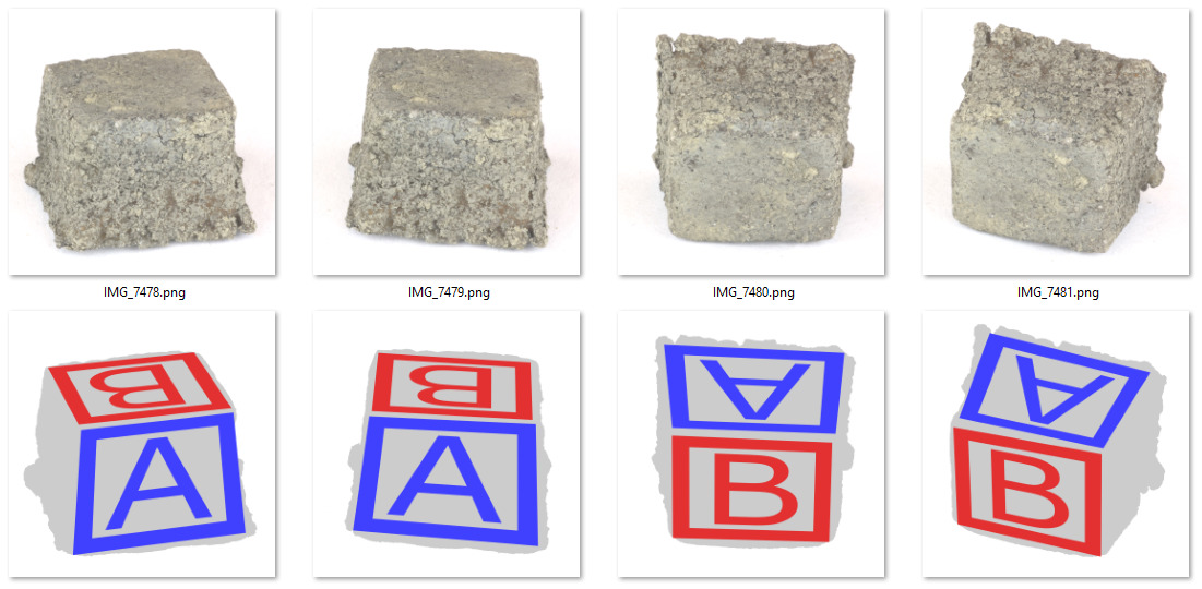 Maintaining visual overlap: We always make sure that consecutive photos see the same part of the object from a similar angle. Typically that can be achieved by rotating the object on the turntable (see images on the left: IMG_7478 to IMG_7479). After a full turntable rotation, we can pick up the object and rotate it so that the same sides of the brick are visible (IMG_7479 to IMG_7480). The previously front-facing side “A” is now facing up. Similarly, the upward-facing side “B” is now facing the camera. For small objects, we generally prefer to move the object and not the camera to keep the workflow fast (otherwise we have to adjust the camera, the focus settings, etc.).
When scanning the 16 salt dough bricks, we realized that manually moving the camera to get a different angle of the object is just too time-consuming. It proved to be much faster to take a brick off the capture stage and rotate it so that the front-facing side is now facing up (and vice versa). This way there is still enough visual overlap (both sides were visible in the previous photo) and we could continue without moving around and refocusing the DLSR camera.
 Facing the stick from its side (left, IMG_8839) is the ideal capture position: The stick covers 18% of the total image (that’s not great but gives a decent area for the software to look for visual information). After rotating the turntable a bit, the situation becomes more challenging. Some areas are observed at a very steep angle (middle image, blue area marked with “X”) and might even disappear in the next image (IMG_8870 on the right). Also, only 8% of the image are occupied by the actual object. That’s why we suggest rotating the turntable in smaller increments (4.5°) in these challenging situations, so there is less visual difference.
Some objects with elongated or flat shapes are challenging to scan because they offer a lot of visible texture from one side but are hardly visible from another angle. Typical elongated objects are the pieces of wood we scanned. When photographed from the side, the object takes up a lot of space in the image and allows the software to pick up a lot of visual information. But when looking directly onto its ends, much less surface area can be observed and processed by your photogrammetry tool. Here it helps to shoot images at shorter intervals. In our setup, we typically capture a photo after revolving the turntable by 9 degrees (40 photos for a full revolution). For those challenging parts, we took a picture every 4.5 degrees.
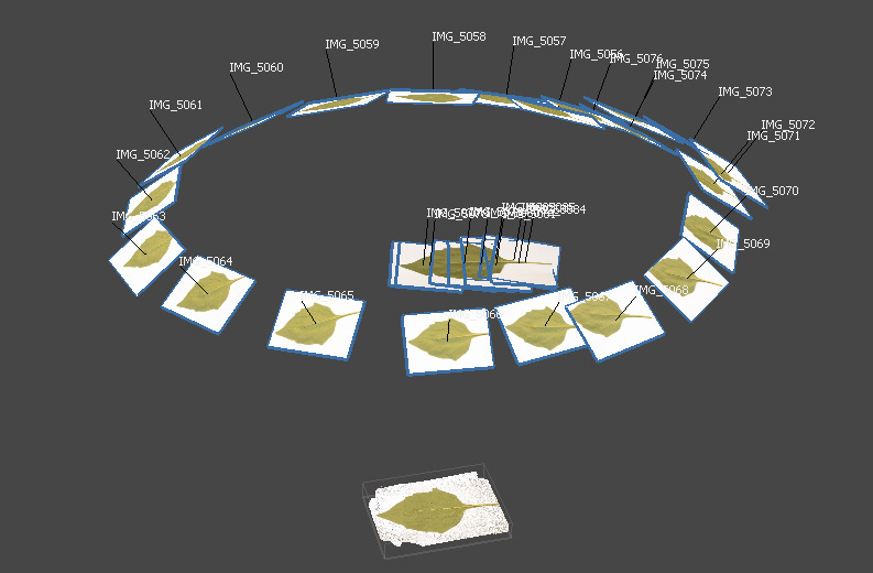 Single-sided scan of the leaf (only object not captured on the turntable): It was too impractical to capture the front and back sides of the leaf in a single session. We decided to scan both sides individually and merge the two meshes in Blender. If you plan to capture flat objects in a single session, we suggest building a capture stage as described in the Playroach blog post.
An example of a flat object is a leaf: It shows a lot of visual information when taking pictures from its front or back. When looking at it sideways, it covers only a few pixels in the image and your photogrammetry software will have a very hard time reconstructing it at all. You can also think about introducing other objects into the scene that can be removed later from the model (but help to give the photogrammetry software more context). This way there’s always at least one object that provides enough visual information. We used this strategy when designing the capture stage in the Playroach project. When scanning the leaf, we captured the front and back separately, the leaf was just too wobbly to put it upright. The drawback was that we had to manually align the two scans in Blender later on.
3. Texture Swapping
For this trick, you need to familiarize yourself with the different workflow stages of photogrammetry software. For a typical scanning session the same image footage can be used for all stages: In some cases, a deeper understanding of how data is processed can come in handy: There are three main stages.
Alignment
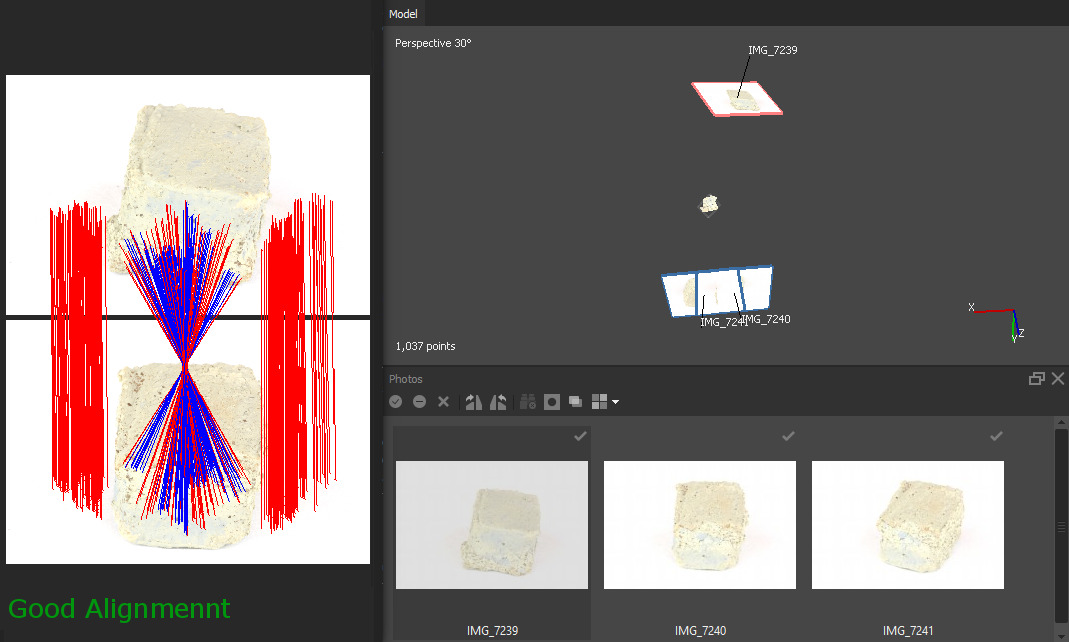
First, the software is figuring out how the cameras are placed relative to the object (“Alignment Phase”). Since some surface points of the object are reconstructed as a by-product, this is sometimes called the “Sparse Reconstruction Phase”. For this phase, the scanned objects have to show some visible texture on all captured photos. For best results in this phase make sure that all image content is part of the foreground object OR moves consistently with it. When we took images of the bricks, we would take the brick off the capture stage after a full 360-degree rotation, turn them around, and put them back on the capture stage. As you might remember, this made it easy to ensure that there’s enough visual overlap between photos while making it possible to see the bricks from all sides. However, it is crucial to exclude as much of the background texture from the actual photographs as possible. Otherwise, the photogrammetry software might be tricked into thinking that we want to reconstruct the white paper and that the gray brick is just a background object (instead of the other way around). We used the “convert” and “mogrify” command-line tools from ImageMagick to modify whole batches of images with a single command. We increased the brightness so most part of the light background would be a uniform (255,255,255) white color. This way the photogrammetry software will not find any visible information in this area. You might also want to experiment with other ways to automatically produce foreground masks (e.g. with the threshold command), but we found the brightness modification to be the quickest solution.
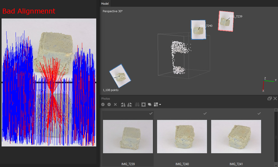 Photogrammetry is very sensitive to texture information. It can pick up the texture of the seemingly white paper (blue lines) and might not pick up enough information from the actual brick in the foreground (red lines) – this results in a “Bad Alignment”. If we boost the brightness of the images so that most background color clips at the maximum brightness value, it produces a “Good Alignment” by matching the foreground (blue lines) and discarding the few background matches (red lines).
Dense Reconstruction
The second phase is the “Dense Reconstruction” phase. Here the software reconstructs the actual surface geometry of your object. For this part, it is crucial that each part of the surface is visible in high detail in at least two photographs (to enable stereo matching). Make sure that all foreground objects are well exposed (if you excessively boosted the brightness during the “Alignment” phase swap those images back for their original well-exposed versions). MetaShape explicitly allows swapping textures (right-click an image and select “Change Path…”). In RealityCapture you have to close the applications, manually delete the temporary cache, swap out the image files on your hard drive, and start the software again. If the photos still lack texture in certain areas, you can apply simple tricks: At the end of the capture session do some additional photographs and apply some (coffee) powder or other visible texture (make-up or removable paint) onto the object surface. Make sure not to use these ‘modified’ images for the “Texturing” phase.
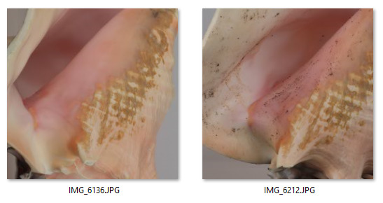 After collecting enough photos from all sides, you can create additional surface texture to provide more visual context for your photogrammetry software. Use all images for Alignment and Dense Reconstruction, but make sure to exclude the ‘modified’ images (image on right) from the Texturing phase.
Texturing
The third phase is the “Texturing” of your object. The images from all different views contribute to a single texture of the object. Here it is crucial that you prevent any photos that show ‘modified’ surface areas from contributing to the result. Also, make sure to exclude under-/overexposed images from this phase. Both MetaShape and RealityCapture let you exclude photos from the Texturing phase.
4. Destructive Scanning
If you are scanning items of low monetary and emotional value, you might consider modifying or completely destroying them during the process to make your life easier. One option is to hand paint or airbrush surface texture onto the model. Similar to the coffee powder trick you get additional texture information that is extremely helpful for the “Alignment” and “Dense Reconstruction”. The drawback is that you need to find a good alternative approach to get a good surface texture. For simple objects like this candle, manually defining the surface appearance might be a solution.
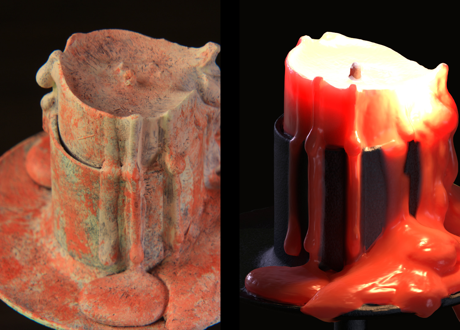 For an earlier scan, we covered a candle with acrylic paint (left). This produced a lot of texture and gave great reconstruction results. The drawback is that we had to recreate the surface material manually in Blender (right). Since the object mainly consisted of only two materials (wax and metal) and we did a manual retopology anyway, this could be done within a reasonable time span.
Another way to modify the object is to actually cut away pieces. We did this for the mushrooms since it was too much of a hassle to make them stand upright on their stem. We cut away their stems before taking photos of their caps. Do not use photos that show the “cut away” parts for Dense Reconstruction (more on that in the “Visibility Consistency Filtering” section) Pro tip: After cutting the mushroom you can actually fry and eat it, it’s yummy!
 Cutting away pieces of your object can simplify the workflow. After we were done taking pictures of the stem and the surrounding area, we cut it off and turned it around. By doing so, the mushroom would simply lay flat on the turntable and we could continue capturing photos of the mushroom cap. Keep in mind not to take photos of the region that was cut away (red “X”). Also do not take photos of areas that would have been occluded by the stem! Otherwise, the “Visibility Consistency Filtering” (see below) might kick in and remove the stem from the reconstructed model.
5. Feed Images in Right Order
The Alignment phase in photogrammetry produces very different results based on the order in which images are processed. There are different strategies for different tools: In RealityCapture, the alphabetical order of images is important. Try to always have enough visual overlap between two consecutive images. RealityCapture is smart enough to realize when two images do not see the same side of your object, but it doesn’t hurt to help. MetaShape solves that problem for you by matching all possible image pairs first. In a second pass, it selects the best pair to start with and incrementally adds other images with high visual overlap. This strategy makes sense but might fail if the initial pair is not the optimal one. A good initial pair should have crisp textures in all parts of the images, the object should be fully visible, and the camera should have moved around the object by approx 5-10 degrees (that number varies a lot for different objects, experiment!). In MetaShape, you can force the software to add photos in a particular order. First, select all images, open the context menu, and select “Reset image alignment”. Now you can pick an optimal image pair and click “Align Selected Cameras”. Now keep adding new images by selecting them individually and by clicking “Align Selected Cameras”. You can of course let MetaShape align multiple or all remaining images at once, but keep in mind that it then decides on its own in which order it adds them.
6. Visibility Consistency Filtering
RealityCapture enforces visibility consistency of the surfaces scanned with the software, and we would like to show how you can use this to your advantage. In plain English, that means that spurious clutter during reconstruction is removed in favor of surfaces that are consistently observed from multiple angles. If you would like to read up on this algorithm, the Patch-Based Multi-View Stereo paper is a good (but heavy) read. The filtering is explained in Chapter 3.3, fig. 5. Knowing about this filtering step is very helpful for turntable scanning. Typically, the software will reconstruct some geometry during the ‘Alignment’ phase that is not part of the foreground object, for example, the white paper that is beneath the mushroom.
 Visibility Consistency Filtering workflow for RealityCapture: (Left) After a full rotation of the turntable, all surfaces in light green are reconstructed. We reposition the brick so its bottom part becomes visible and start another turntable rotation (second image from left) – all parts in dark green are reconstructed. When reconstructing the object’s geometry, RealityCapture deals with conflicting information (second image from right): In some areas, there are two conflicting surfaces – the brick and the white paper (red circles). RealityCapture resolves this conflict with Visibility Consistency Filtering and presents us with a result (rightmost image) that can be cleaned up after photogrammetry is finished (we used Blender).
When we turn the brick around to take pictures of its other sides, RealityCapture does not see any paper covering the brick that was previously observed at the bottom part of surface “A” and will filter out this geometry during the reconstruction phase. It’s very important to keep that in mind when doing destructive operations (as described above). In the case of the mushrooms, we cut away the stem so it could easier stand on the flat surface. We had to make sure that the ‘cut away’ part of the mushroom does not become visible in any other photos, otherwise Reality Capture might have filtered out the stem of the mushroom.
MetaShape does not have such a filtering step (or at least it’s not as pronounced). In order to get great results here, we recommend putting objects on a small pedestal (can be a small wooden block, a piece of blu tack, a rubber band, etc.). It’s important that the region where your scanned object touches the pedestal is never visible in any of the photos. If you follow this rule, it’s very easy to remove any 3D clutter after Dense Reconstruction (using MetaShape’s lasso tool) or even after the Meshing phase (by removing any spurious blobs of geometry in your 3D software). You have to make sure to remove any excess geometry before the Texturing phase, though.
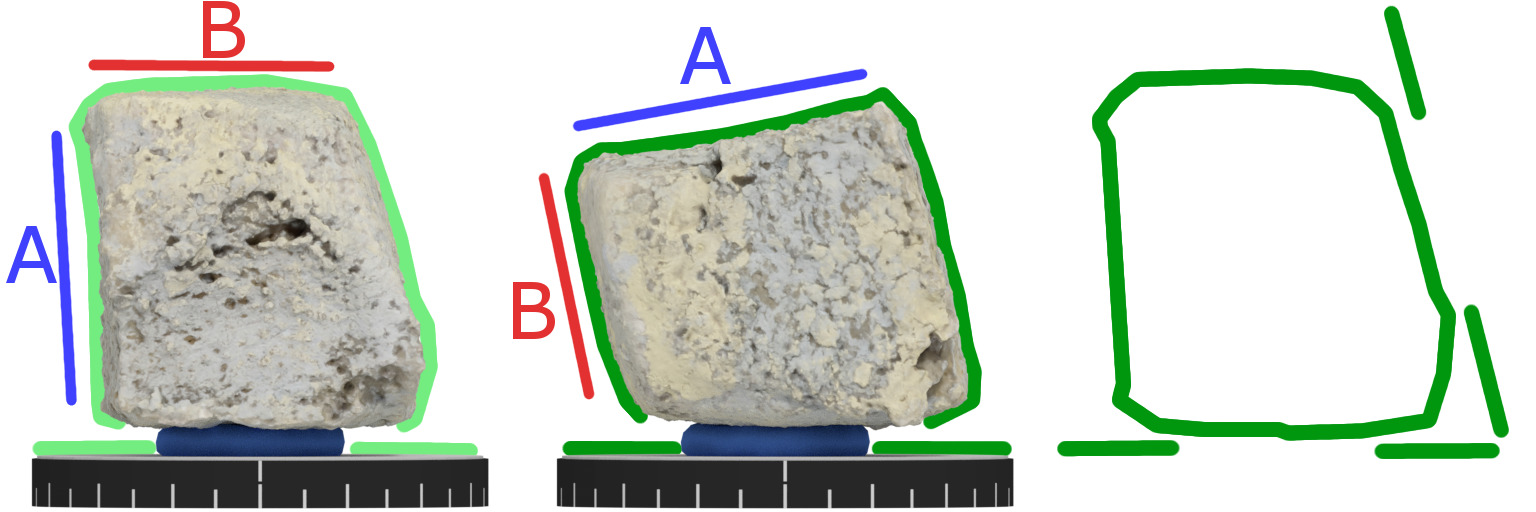 MetaShape workflow: We put the object on a piece of blu tack and use the same procedure as described above. Although no additional filtering is performed by the software, all reconstructed parts of the background and foreground are spatially separated (right). The unwanted parts of the background should be discarded with MetaShape’s “Resize Region” or “Freeform Selection” tool before going to the “Build Texture” phase.
If your capture material shows the areas where the objects touches the background or pedestal, removing the faulty geometry becomes a very tedious process and you might want to recapture that material.
7. Consider a JPEG Workflow
As you might have realized, we are using .jpg images throughout the workflow. We realize most tutorials strongly suggest using raw image formats. In our experiments, we of course realized that there is a measurable quality difference, but often do not find the ‘extra effort’ for using raw is justified. One drawback of raw is of course file size, but we also find them harder to work with since many tools do not support raw images. Similar thoughts apply to other aspects such as image resolution. In general, bigger is better, but for some workflows, the highest settings might lead to unbearable processing times and will just cram your hard drive with unneeded pixels. Always try to strike a balance between resolution/quality and your (system’s) ability to actually handle the data. Especially when you’re in the experimenting phase of a new project, you don’t want to stare at progress bars for most of your day.
8. Blank Photo
This trick is almost too simple to mention: When you photograph similar objects, always record a ‘blank’ photo (without any foreground elements) before starting with the next object. This way you can easily distinguish between data for different objects.
 Take a blank photo of the turntable between scanning different objects. Especially if they look alike, it helps to easily tell when one capture session ended and the next one began (IMG_2791).
9. Don’t Follow Instructions
Yes, that’s right, you shouldn’t trust all advice you read here. There’s tons of other helpful but conflicting advice out there. Do your research and read all the relevant tutorials you can find. But at the end of the day, you have to experiment and see for yourself what works out best for your project.
Have fun creating!
-Kathrin and Christian
Sticks and Stones by Kathrin&Christian on Sketchfab
